Translation:
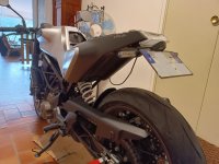
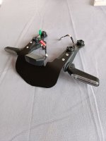
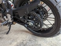
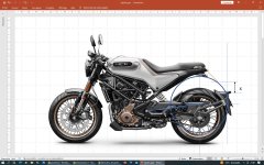
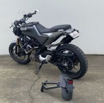
The travel is to be measured vertically, not according to the radius of the wheel, which makes it possible to reduce the angle of the license plate. Namely that when the motorcycle is on its wheels, the depress of the rear suspension is already about 15 mm, 50 mm rider sitting on the motorcycle stationary. I have a new 2021 model recently, I will do the operation of transferring the license plate under the taillight by myself. To check if there is plate-tire interference when the suspension is fully depressed, I plan to do a static test by compressing the suspension with a ratchet strap attached between the oscillating bars and the rear frame. If the tire touches the plate, due to the direction of rotation of the wheel, the plate will be swallowed.


")